Microsoft Visio is an advanced drawing and diagramming software designed to allow a user to create organizational charts, network diagrams, value streams, business process flowcharts, and more.
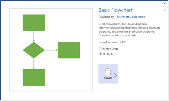
Microsoft Visio provides intelligent templates and shape stencils to jump start diagramming. For the creation of a business process flowchart, the ‘Basic Flowchart’ template is used most frequently.
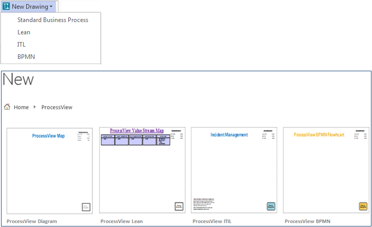
Note that the 'New Drawing' button on the ProcessView ribbon provides access to a number of ProcessView drawing templates that may be used to start flowchart construction.
To create a drawing with the Basic Flowchart template, follow the instructions below:
Visio 2013
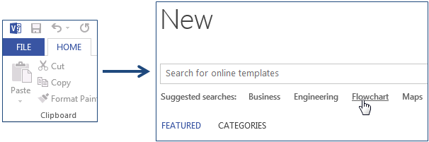
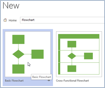
Access the Visio File tab, select ‘New’, and find the ‘Flowchart’ option in the Template Categories. In the Flowchart template options, select the Basic Flowchart (US Units) and click ‘Create’.
Visio 2010
Access the Visio File tab, select ‘New’, and find the ‘Flowchart’ option in the Template Categories. In the Flowchart template options, select the Basic Flowchart (US Units) and click ‘Create’.
Visio 2007
Access the Visio File menu and expand the ‘New’ options. Select ‘Flowchart’ folder and choose the ‘Basic Flowchart (US Units)’ option.
Visio 2007, 2010, and 2013
Note that when a drawing is created with the Basic Flowchart Template, the Basic Flowchart Stencil is opened to provide shapes for drawing. To add a shape to the drawing canvas, simply use the left mouse button to click on the desired shape in the stencil; while continuing to hold down the left mouse button, drag the shape from the stencil onto the canvas.
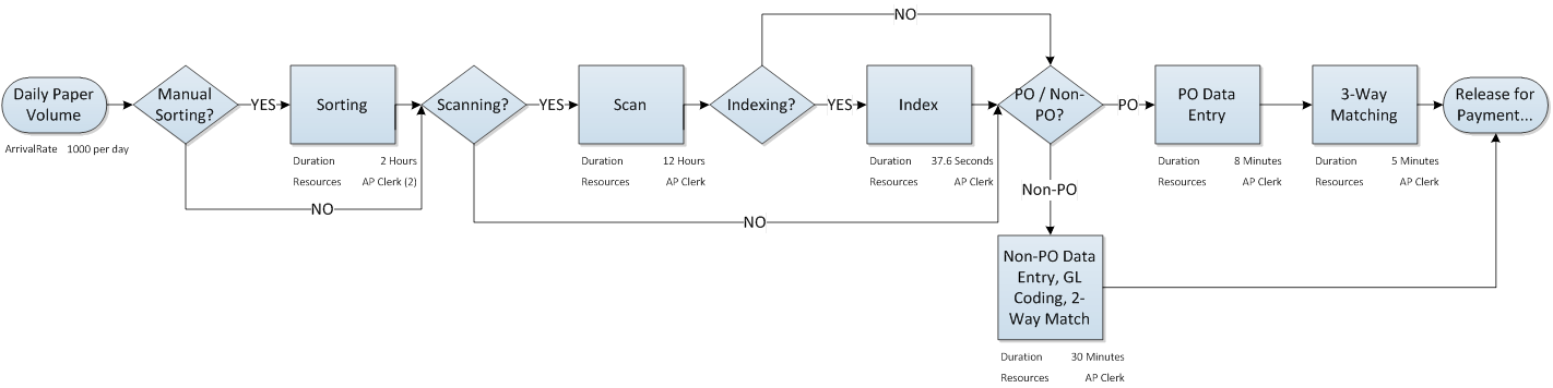
The ‘Start/End’ shape, called a ‘Terminator’ shape in Visio 2007, if used to represent a start or end point in the process.
The ‘Process’ shape is used to represent an activity, procedure, or step in the process flow.
The diamond ‘Decision’ shape, as the name implies, is used to represent a decision in the process; think of these as traffic directors for demand.
An example flowchart is shown below.
Note that ProcessView does not require that these shapes be used to construct a process model. ProcessView supports the use of any two-dimensional Visio shapes for starts, activities, decisions, and ends. What is of primary importance when using ProcessView is that the shapes used to construct the process flowchart be firmly connected together. To connect shapes, the connector tool can be used.
Visio 2013
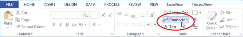
In Visio 2013, the connector tool is located in the ‘Tools’ section of the ‘Home’ tab.
Visio 2010
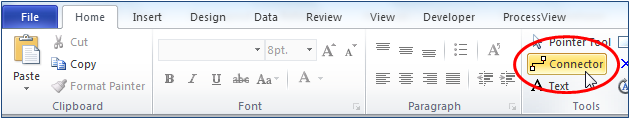
In Visio 2010, the connector tool is located in the ‘Tools’ section of the ‘Home’ tab.
Visio 2007
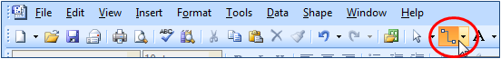
In Visio 2007, the connector tool is located on the ‘Standard’ toolbar. If you do not see the standard toolbar shown below, access the Visio View menu and select ‘Standard’ from the ‘Toolbars’ menu.
Visio 2007, 2010, and 2013
As an alternative to the connector tool, connector shapes may be dragged and dropped onto the page from a shape stencil.
Visio 2007
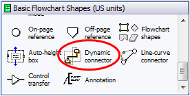
In Visio 2007, the Basic Flowchart Shapes Stencil contains a dynamic connector shape.
Visio 2010 and 2013
In Visio 2010 and 2013, a stencil containing connector shapes can be accessed through the ‘More Shapes’ option in the Shapes window; choose ‘Visio Extras’ and locate the ‘Connectors’ stencil.
Visio 2007 and 2010
When connecting shapes, it will be useful to ensure that the shape connection points are visible.
Visio 2010
In Visio 2010, connection points are presented with blue arrows when the cursor is placed over a shape. Note that you can use the left mouse button to click on the blue arrow and, while continuing to hold down the left mouse button, drag the mouse to create an outbound connector.
If you do not see these arrows, access the View tab on the Visio ribbon and check the ‘Connection Points’ option in the Visual Aids section.
Visio 2007
In Visio 2007, connection points are presented with blue x’s when the cursor is placed over a shape.
If you do not see these x’s, access the Visio View menu and check the ‘Connection Points’ option.